3D aircraft propellers
- Luca

- 7 ene 2022
- 1 Min. de lectura
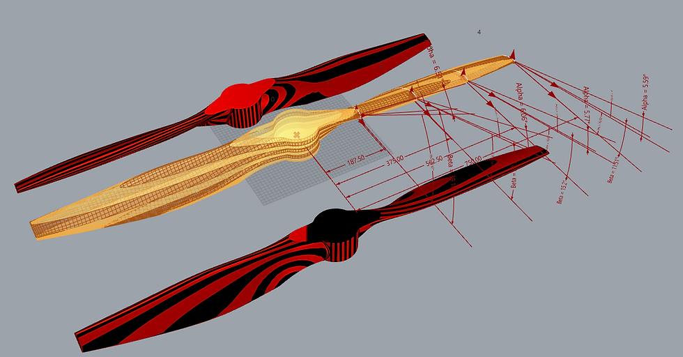
At the request of a prop manufacturer I made a definition in Grasshopper for the rapid drawing of propellers. shape control is total radius of the helix pitch, number of stations, profile for each station with the possibility of assigning the angle of incidence, length of each string and any dimensions to near the hub to customize the fitting.

The pitch variation can be chosen so that the aerodynamic angle of attack is, around 70-75% of the radius, that of greater efficiency. The control you have of the shapes allows you to make quick changes and then reprocess the 3D model with a CFD solver.


Phi is the angle of the resulting wind speed vector (V_air + V_peripheral, see images above) and is calculated after assigning the motor rotation speed in RPM and the forward speed (opposite).
The Reynolds coefficient at each station (below) and the solidity are calculated. The calculation of the traction is done with Xrotor which can be downloaded free of charge from qui.
Below is a summary of the inputs and outputs returned by the modeling program:

The aforementioned propeller was studied in Xrotor by setting the aerodynamic data of the Clark-Y profile taken from the airfoiltools.com site and the geometric data obtained from the 3D drawing and listed above.

The propeller, from a first preliminary approach, seems to have good characteristics in terms of performance and traction. The next step is the prototyping and verification of the data obtained.
The resulting surface is in fact closed and ready for 3D printing or NC processing.

Below a rendering.


Below is a short demonstration video even if not updated.


